


 Cassette
 Apron
Apron Screen
 DAP
DAP AEC Chamber
 PAG
PAGBack to List Page 


General
- During an X-ray exposure a dose equivalent ionization current is
generated in the AEC Sensor and a corresponding cut-off signal is
created and transferred to the X-ray generator.
The AEC sensor ensures a reproducible optimal exposure independently of beam quality, patient thickness and any other factors. Using an AEC sensor avoids over or underexposure of the image and helps to reduce patient dose.
The AEC sensor ensures a reproducible optimal exposure independently of beam quality, patient thickness and any other factors. Using an AEC sensor avoids over or underexposure of the image and helps to reduce patient dose.
Configuration
-
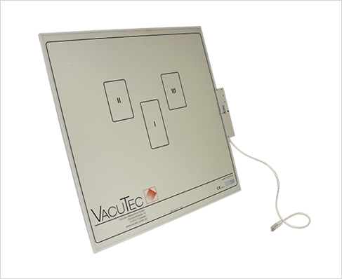
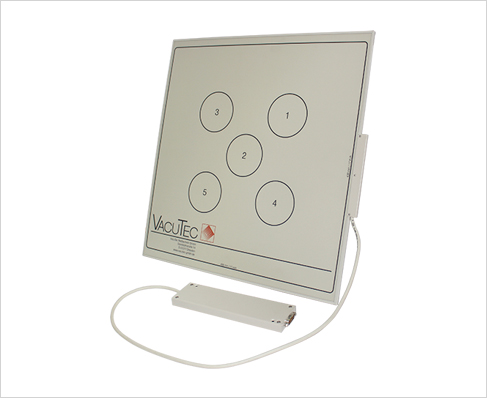
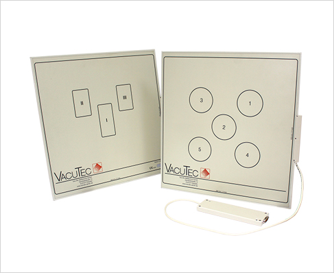
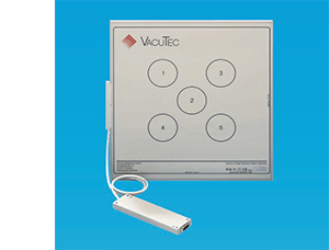
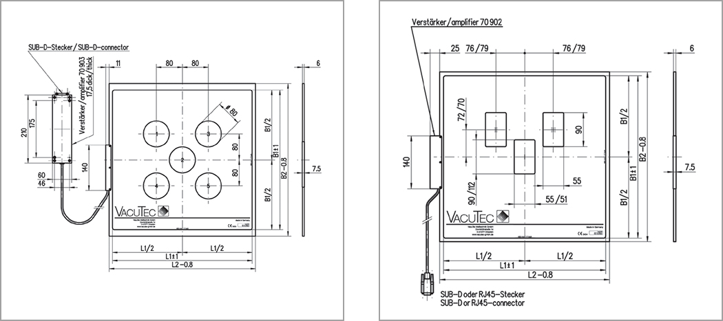
The ionization chambers for AEC are air-filled parallel-plate chambers with typically one, three or five independent sensor fields. Several different outer dimensions are available.
Each VacuTec ionization chamber is equipped with a preamplifier and electronics, which converts the low ionization current into EMC stable digital signals (see figure below). Additionally it supplies the voltage for the chamber operation and allows selection
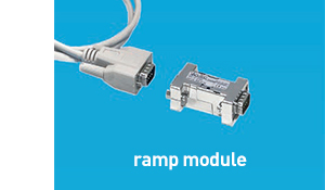
of the sensor fields. Optionally the digital output signal can be transformed into an analogue voltage by using an additional ramp module.
The positioning of the AEC sensor is close to the image detector. If an anti-scatter grid is used, the sensor has to be placed between the grid and the image detector. The AEC sensor has to be connected to an automatic exposure controller at the generator site.
Calibration
- Each VacuTec AEC chamber is factory calibrated to radiation quality RQA5.

| Part No | No. of Measuring fields | Connector | size (mm) |
| 142 00 17 | 1 | Sub-D 9 pin | 140 x 140 |
| 142 00 13 | 1 | Sub-D 9 pin | 374 x 374 |
| 142 00 14 | 1 | RJ45 | 374 x 374 |
| 141 00 18 | 3 | Sub-D 9 pin | 374 x 374 |
| 141 00 19 | 3 | RJ45 | 374 x 374 |
| 145 00 44 | 3 | Sub-D 9 pin | 450 x 450 |
| 145 00 45 | 3 | RJ45 | 450 x 450 |
| 151 00 21 | 3 | Sub-D 9 pin | 450 x 450 |
| 151 00 22 | 3 | RJ45 | 450 x 450 |
| 139 00 03 | 5 | Sub-D 15 pin separate electronics | 450 x 450 |

| Part No | Description |
| 902 00 42 | for 1 and 3 field AEC chambers |
| 902 00 11 | for 1 and 3 field AEC chambers, with cable extension |
| 903 00 11 | for 5 field AEC chamber, with cable extension |

| Energy range/tube voltage | (40 ... 150) kV |
| Dose rate range | (0.5 ... 1000) μGy |
| Exposure dose range ¹) | (1 ... 100) μGy |
| Digital resolution (selectable) | 0.025 μGy |
| Eposure time range ¹) | 1 ms ... 10 s |
| Sensitivity difference between sensor fields | <5% |
| Attenuation factor ¹) | <4% |
| Aluminium equivalent | < 0.75 mm Al |
| Supply voltage (positive and negative) | ± (11.5 ... 16) V DC |
| Digital output | Differential signal (RS 422), pulse width 2 μs |
| Ramp output (with ramp module) | 0 ... 10 V |
¹) According to DIN 6815 dose measurement is carried out as follows: the air kerma (in Gy) is measured immediately downstream of the combined scattered-ray grid/measuring chamber using a radiation quality attained at a high-voltage of (70...80) kV and an Al
attenuation layer thickness of 25 mm
For detailed technical information please require our documents.
For detailed technical information please require our documents.


Copyright(c) JPI All Rights Reserved. 
서울특별시 구로구 디지털로33길 28 608호 (우림e-biz1차) (08377) l Tel. 02-2108-2580 l global@jpi.co.kr
서울특별시 구로구 디지털로33길 28 608호 (우림e-biz1차) (08377) l Tel. 02-2108-2580 l global@jpi.co.kr